Angle Position Indicator
Model 8810A: Angle Position Indicator (API) is a rack mount or benchtop measurement instrument featuring two fully independent inputs that can be used to read two separate input signals simultaneously, or can be combined to measure multi-speed Synchros or Resolvers. Improved flexibility is provided by front panel controls and input terminals.
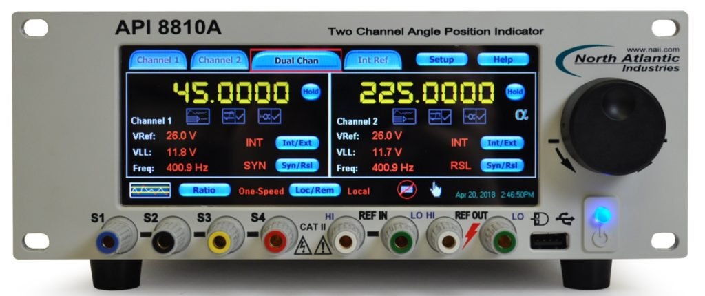
- Resolution: 0.0001°
- Accuracy: Up to ±0.0015°
- Two Isolated Input Channels
- Single or Two-Speed Measurements: Programmable Ratio from 2 to 255
- Three display modes: 0-360°, ±180° or degrees, minutes & seconds
- Ethernet, USB, IEEE-488, and parallel ports
- Optional 6 VA Internal Reference
Phase Angle Voltmeters
Model 2250A: Phase Angle Voltmeter is the most accurate AC measurement tool in the Synchro/Resolver and LVDT/RVDT. This precision instrument measures total, fundamental, harmonics, in-phase, quadrature, frequency, THD, ratio, and phase angle, and displays all of these measurements at the same time. The isolated inputs enable null, ratio, and gain measurements.
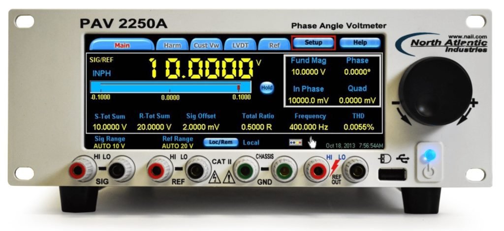
- Two Galvanic Isolated Input Channels (Signal and Reference)
- High Accuracy: 1uV Nulling Sensitivity
- Frequency: Up to 1MHz
- Voltage: Up to 500 Vrms
- Resolution: 0.00001°
- Harmonic Rejection: Up to 80 dB
- Ethernet, USB, and IEEE-488 ports
- Optional 6VA Internal Reference
Synchro/Resolver Simulator
Model 5330A: Synchro/Resolver Simulator is a rack mount or benchtop instrument featuring two fully independent outputs that can be used to simulate two separate Synchro or Resolver signals simultaneously, or can be combined to operate as two-speed outputs. Improved flexibility is provided by integrated touch screen controls and input terminals.
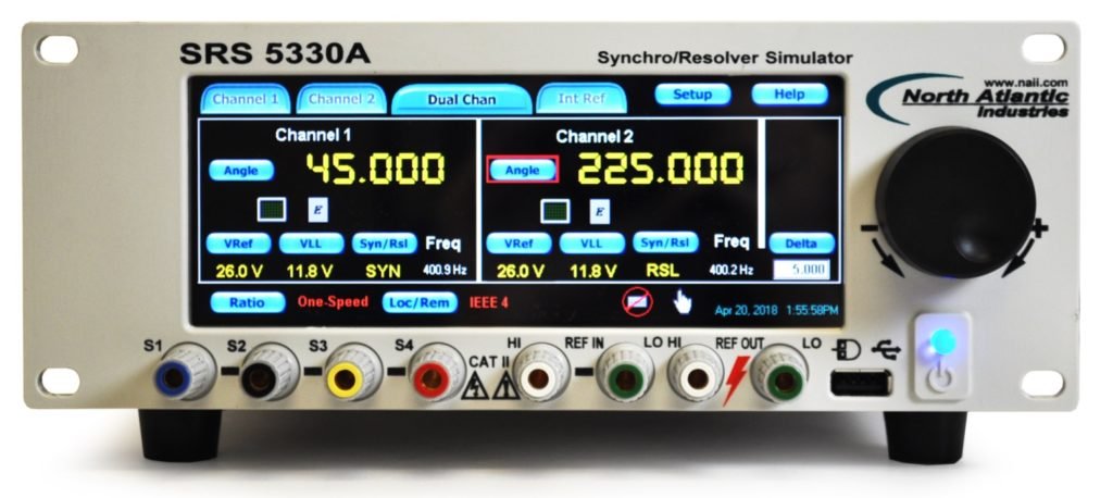
- Resolution: 0.001°
- Accuracy: up to ±0.003°
- One or Two Output Channels (Up to 6 VA per channel)
- Single or Two-Speed Simulation: Programmable Ratio from 2 to 255
- Two display modes: 0-360° and ±:180°
- Ethernet, USB, IEEE-488, and Parallel ports
- Optional 6 VA Internal Reference
High Accuracy Model 5300: This model can be used as a true Synchro/Resolver standard for calibrating and testing Automatic Test Equipment (ATE) for Calibration/Metrology Labs, and for Engineering Design and Production Test environments. It can also be used to measure Angle Position Indicators (API) and Synchro-to-Digital converters for static or dynamic characteristics.
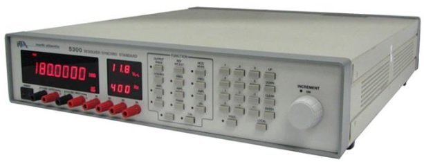
- 0.0001° Resolution
- 2 arc second accuracy
- Continuous CW or CCW rotation to 100,000°/sec
- Frequency: 47 Hz to 20 kHz
- Static or continuous Synchro/Resolver rotation simulation, from slow roll to fast slew rates
- Built-in reference generator
- Rack-mount or benchtop installation
JTAG Boundary Scan Solutions
Hardware – JTAG Boundary-Scan Controllers
NetUSB II: High-performance, multi-feature boundary-scan controller for multi-TAP and concurrent JTAG test and in-system programming. Featuring dual-interface USB and LAN support with four or eight independent and configurable Test Access Ports (TAPs), direct serial programming capability and voltage sense support, the NetUSB II fits a multitude of boundary-scan applications.
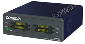
- 4 or 8 TAP connections
- User-programmable JTAG TCK rate up to 100 MHz
- Independently configurable output voltage and input voltage threshold
NetUSB-1149.1/E: High performance, multi-feature boundary-scan controller for multi-TAP and concurrent JTAG test and in-system programming. Featuring dual-interface USB and LAN support with four independent Test Access Ports (TAPs), direct serial programming capability and voltage sense support, the NetUSB-1149.1/E fits a multitude of boundary-scan applications.
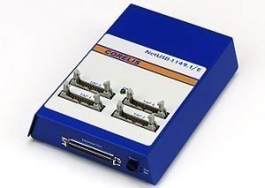
- 4 or 8 TAP connections
- Concurrent (gang) testing and In-System Programming (ISP) on up to four UUTs for high volume test.
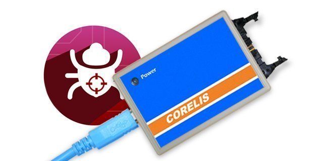
USB-1149.1/1E: USB-1149.1/1E High-Speed single-TAP boundary-scan controller is a powerful, portable USB JTAG instrument for all JTAG applications and life cycle phases. Works with the complete Corelis ScanExpress™ family of software, enabling comprehensive test coverage at a fraction of the cost of traditional bed-of-nails testers and without the inconvenience of fixtures.
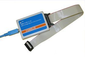
- 1 or 4 TAP connections
- User programmable JTAG TCK rate up to 100 MHz, SPI SCK rate up to 50 MHz, and I2C SCL rate up to 5 MHz.
SCANIO: SCANIO modules turn any IEEE standard 1149.1 boundary-scan controller into a powerful digital boundary-scan tester. The SCANIO family of products use boundary-scan gate arrays to add control and visibility to connectors, traces, and logic that can not be tested using traditional boundary-scan techniques.
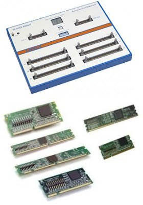
- Digital I/O Module. Upto 300 single-ended or 150 differential individually controlled
- Voltage leve are configurable
- DIMM Socket Tester
- Tests for opens on power and ground pins
JTAG Starter Kit: Debug and visualize prototype hardware faults, even on component pins with no physical access. JTAG Starter Kit provides everything necessary to get started using JTAG, yet still provides a flexible upgrade path to higher performance controllers and integration with high-end Corelis applications.
- Speed up hardware development
- Modular JTAG toolkit
- Reduce debug and troubleshooting time
- Help to eliminating the need to write functional tests.
JTAG 3rd Party Controller Support: Corelis offers support for a variety of devices and instruments from third-parties in an effort to provide existing test platforms comprehensive JTAG test execution with Corelis ScanExpress software products
- ScanExpress supports for third part controllers national Instruments and Teradyne Di Series.
- National Instruments: PXI/PCI-6551/6552, PXIe-6556
- Teradyne Di-Series and HSSub instruments
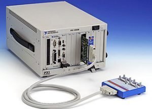
PCIe-1149.1/ PCI-1149.1/Turbo: PCIe/ PCI based Boundary-scan controller for multi-TAP (Test Access Port) and concurrent JTAG test and in-system programming. Combined with a ScanTAP™ intelligent pod, the PCIe-1149.1 offers up to 80 MHz clock rates on 4 or 8 TAPs with features such as external write strobe, direct programming, and analog voltage measurement.
- Save time at test stations
- Reduce costs associated with fixtures
CPXI-1149.1/Turbo: PXI/cPCI based Boundary-scan controller for multi-TAP (Test Access Port) and concurrent JTAG test and in-system programming. Combined with a ScanTAP™ intelligent pod, the CPXI-1149.1/Turbo offers up to 80 MHz clock rates on 4 or 8 TAPs with features such as external write strobe, direct programming, and analog voltage measurement.
- Save time at test stations
- Reduce costs associated with fixtures
ScanTAP 4 & 8: ScanTAP pods are designed for use with PCI-1149.1/Turbo and PCIe-1149.1 high-speed JTAG controllers. Featuring 4 & 8 independent Test Access Ports (TAPs), up to 80 MHz clock rates, and advanced TAP capabilities for high-performance environments.
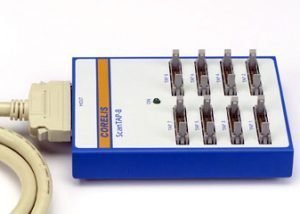
- Save time at test stations
- Increase programming rate
- Reduce costs associated with fixtures
Test and Programming- ScanExpress Software
Test Development System
ScanExpress TPG – Test Pattern Generation: ScanExpress TPG is a next generation intelligent test pattern generator that takes the process of boundary-scan automation to a new level in both performance and ease of use.

- Automatically generates test patterns for components using proven, boundary-scan test algorithms
- Detects and supports all netlist
- Finds and classifies all resistors
ScanExpress JET – JTAG Embedded Test: Used to automatic circuit board testing by extending boundary-scan structural test coverage to virtually every signal on the board that is accessible by an on-board CPU.

- Assists in prototype debug before test firmware or test fixtures
- save coding time through automatic test
- Increase board test coverage.
- field validate a customer board or upgrade firmware on-site
ScanExpress DFT Analyzer – Design for Testability Metrics: Automatic test coverage analysis tool for printed circuit boards and systems for boundary and non-boundary-scan devices. Increase fault coverage and reduce boundary-scan test procedure.

- Validate board test coverage before committing to layout
- Reduce the number of PCB test points
- Find test holes and deficiencies
- Reduce test procedure development time
Test Execution System
ScanExpress Runner – Test Program Execution: Fully featured JTAG test executive; a modern software application that provides the capabilities and options necessary to ensure a smooth and complete testing process.

- Enables boundary-scan test, in-system programming, and JET functional test
- Simplifies boundary-scan test execution
- Increases yields and decreases test time
- Speeds test, diagnosis, and repair of faulty circuit boards
ScanExpress Runner Gang – High Volume Test Program Execution: Workhorse software piece to perform parallel gang testing and In-System Programming of CPLDs and Flash devices.

- Save time by testing up to 8 units simultaneously.
- Increase in-system-programming.
- provides persistent, concurrent scan vector output and extraction, ensuring that effective throughput remains high.
ScanExpress Viewer – Visual Fault Identification System: Powerful graphical fault identification system that helps to isolate source and location of faults encountered during boundary-scan test of PCB.

- Save time and effort at the repair station by visually identifying probable fault.
- Decrease expertise requirements with easy-to-read, graphical fault indicators based on advanced boundary-scan diagnostics.
ScanExpress ADO – Advanced Diagnostics: Fully automated analysis option quickly parses test vectors and identifies faults down to the net and pin level.

- More detailed fault diagnostics than truth-table display
- Non-technical users can quickly assess fault causes
- Spend less time on debug
- Release prototypes more quickly
- Engineers can quickly isolate manufacturing defects from real design problems
ScanExpress Merge – System-Level Interconnect Solution: Designed to import and join test files for multiple independent assemblies and assist in configuration of a combined test procedure..

- Test multiple sub-assemblies with a single test plan
- Increase overall test coverage
- Painless integration of additional boundary-scan IO modules for expanded test coverage.
- photographic visual failure analysis
ScanExpress JTAG Debugger – Interactive Debugging: Provides complete pin control over any boundary-scan device. overcomes these limitations to provide the control and visibility.

- Debug hardware faults in systems with JTAG, even on comp
- Integrate boundary-scan control and test scripts into automated test routines.
- Troubleshoot hard-to-find faults even on BGA and fine-pitch components
Boundary-Scan In-System Programming (ISP) Tools
ScanExpress JTAG Programmer – In-Circuit Programming Tool: Universal in-circuit programming tool that can program and verify Flash memories, serial EEPROMs, CPLDs, FPGAs, and other programmable logic devices.

- Programmer – Direct SPI and I2C, Target Assisted Flash (TAF)
- Quickly erase, program, verify, and read code stored in memory devices
- Allows memory devices to remain on the shelf in a blank state until ready-to-ship, easing inventory management
- Reprogram Flash and troubleshoot firmware problems in the field
ScanExpress Flash Generator – Flash Programming File Generation Tool: Creates a Board File, which is used to provide ScanExpress Programmer with the necessary information to program a target board configuration.

- Can quickly develop in-system programming files for system debug and verification
- combine boundary-scan test and programming to increase throughput
- Technicians can reprogram Flash devices in-system to restore corrupted data or upgrade firmware
- Allows Flash memory to be locked after programming or unlocked for reprogramming
Bus Analyzers And Exercisers
Corelis bus analyzers and exercisers offer analysis, test, debug, and validation capabilities for product development, system integration, and manufacturing of digital boards and systems with I2C and Serial Peripheral Interface (SPI) bus. All of our bus analyzers are PC-based and come with software that runs on Microsoft Windows 7, Windows 8/8.1 and Windows 10.
BusPro-I: Bus Analyzer, Monitor, Debugger and Programmer– Monitor and log I2C bus traffic in real-time, generate I2C transactions to communicate with components on the bus, and perform in-system programming of I2C EEPROMs.
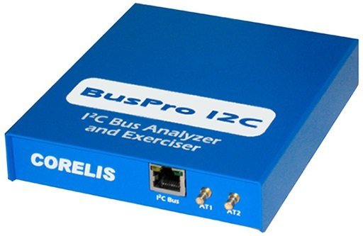
- Monitor displays high-level view of I2C bus traffic
- Allows to Read/write access to peek and poke device registers
CAS-1000-I2C/E: Bus Analyzer, Exerciser, Emulator, and Programmer– Provides functionality of BusPro-I analyzer as well as additional features and capabilities towards automated system test, component verification, and parametric testing.
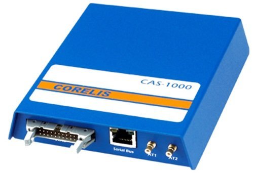
- Monitor and log I²C bus traffic in real-time
- Generate traffic to exercise the bus and communicate
BusPro-S SPI Bus Host Adapter: High Speed Multi-IO SPI Host, Debugger, and Programmer -Featuring 60 MHz upto 200 Mb/s throughput and supports standard, dual, quad, and 3-wire modes, BusPro-S is right tool for all SPI debugging applications.

- Generate SPI bus traffic and interface with peripheral components.
- Read, erase, program, and verify SPI Flash Memories.
Highspeed DAQ Cards
VME Bus
Master/ Controller
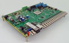
SIS3153 USB3.0 AND ETHERNET TO VME INTERFACE: Superspeed USB performance without the need for a PCI add on card. No system shutdown/reboot time.Ethernet to VME Interface with GBit/s Copper SFP Medium
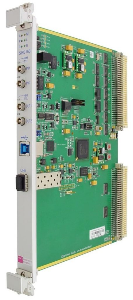
- Single width 6U VME master/system controller
- USB3.0/Superspeed USB functionality
- USB2.0 and USB1.1 compatibility
- 2 inputs/2outputs 00 LEMO, NIM/TTL level programmable
- SFP cage for optical or Ethernet link
- all relevant VME addressing modes up to SST.
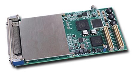
SIS3104: With one Gigabit/s link speed firmware it is backward compatible to the SIS3100 standard model and be used as a drop in replacement. Transfer rates in excess of 160 MByte/s are possible im combination with the SIS1100e single lane PCI Express card.
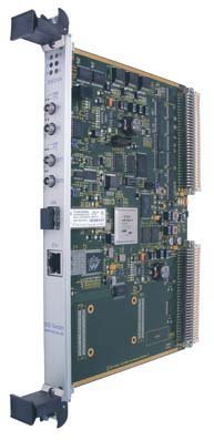
- Single width 6U VME master/system controller
- 1/2/4 GBit/s optical link
- 10/100/1000 MBit/s Ethernet
- 128 MBytes memory (PPC Ethernet or VME slave)
- 2 inputs/2outputs 00 LEMO, NIM/TTL level programmable
- FLASH memory (to load PPC)
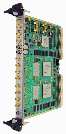
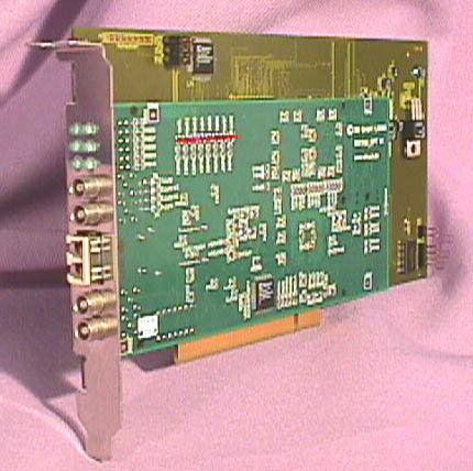
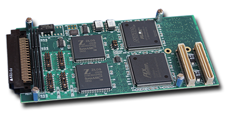
SIS1100-ECMC PCI EXPRESS CMC CARRIER/OPTICAL LINK BOARD: Single lane PCI express CMC carrier to be used with CMCs like the FZ Jülich ZEL Scaler CMC. For our PCIe to VME interface or frontend readout systems it is stuffed with one small form factor (SFF) 1/2/4 G link medium.
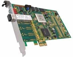
- single lane PCIe card
- PLXtech PEX8311 PCIe to local bus bridge
- Xilinx Virtex 4 FPGA
- single CMC site
- SFF 1/2/4 GBit/s optical link option
- In field JTAG and PCIe firmware upgrade capability
Analog to Digital Converter (ADC) Cards
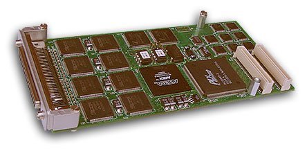
SIS3302 8 CHANNEL 100 MS/S 16-BIT ADC: Used to readout of high resolution detectors, accelerator controls and other applications.
- 8 channels
- 100 MS/s per channel
- 16-bit resolution
- > 13 effective bits
- 32 MSamples memory/channel
- 16-bit offset DACs
- 50 MHz bandwidth
SIS3305 2/4/8 CHANNEL 5/2.5/1.25 GS/S 10-BIT VME DIGITIZER: 8 channel 6U VME digitizer/transient recorder with a sampling rate of up to 5 GS/s (for the individual channel) and 10-bit resolution.
- 2/4/8 channels
- 5 GS/s/2.5 GS/s/1.25 GS/s per channel
- 512/256/128 MSamples/channel memory
- 2 GHz bandwidth
- Internal/External clock
- readout in parallel to acquisition
SIS3316 16 CHANNEL VME DIGITIZER FAMILY: Readout in parallel to acquisition. Pre/Post trigger capability.Single width 6U VME card
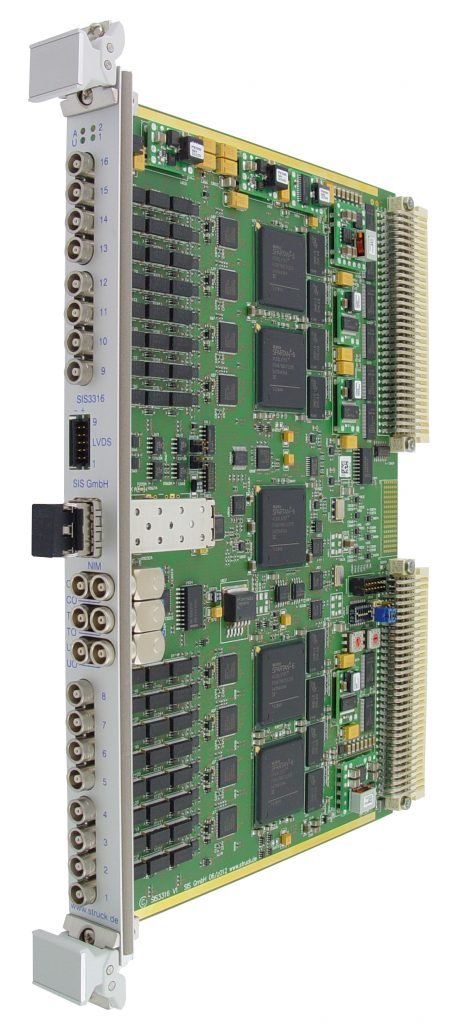
- 16 channels
- 125/250 MS/s per channel
- 16-bit/14-bit resolution
- 64 MSamples memory/channel
- Two programmable input ranges
- 50 Ω or high impedance programmable
- Offset DACs
- 62.5/125 MHz analog bandwidth
DIGITAL I/O
SIS3600 32-bit VME Multi Event Latch: Latch firmware implementation on the base of the SIS360x/38xx base board. The module is designed as a multi event latch with a default FIFO size of 32 K events, 128 K events can be implemented as stuffing option.
- 32-bit
- ECL, NIM, TTL or LVDS input levels
- 32 K (128 K optional) events
- FIFO structure
- Fast OR output
- Fast clear capability
SIS3601 32-bit Output Register: Auto event number increment mode makes the unit perfectly suited to distribute event numbers in larger scale VME data acquisition systems.
- 32-bit output
- Data valid/write strobe output
- pulse and level mode
- ECL, NIM, TTL or LVDS levels
- Event number auto increment mode
- Multiplexer and multiplexer data register
SIS3610 16 In/16 Output Register: Unit looks exactly like the SIS3800 flat or SIS3800 LEMO units, in the case of NIM and ECL ouput levels special driver piggy backs are installed
- 16-bit Input/output
- ECL, NIM, TTL or LVDS levels
- 4 user outputs/Flipflops coupled with LED
- 4 control inputs
- VME Access/user LED
SIS3320-250 8 CHANNEL 250 MHZ 12-BIT ADC/DIGITIZER: 8 channel 6U VME digitizer/transient recorder with a sampling rate of up to 250 MHz (for the individual channel) and 12-bit resolution.
- 8 channels
- 250 MHz per channel (40 MHz – 250 MHz)
- 32MSamples/channel memory (64 MSample option)
- 100 MHz bandwidth
- Offset DACs
SCALERS / COUNTERS / MULTISCALERS
SIS3820 scaler is a single width 6U VME card, no non standard voltages are required. The unit comes with a 20 pin header connector for the control section and two 34 pin headers for the counters (ECL and flat cable TTL version) or via 8 LEMO connectors for the control section and 32 LEMOs for the counter section (NIM and LEMO TTL version). RS422/RS485 is available as input option.
- A16/A24/A32 D16/D32/BLT32/MBLT64/2eVME/CBLT
- VME interrupt capabilities
- Broadcast features
- 32 channels (+32 channel option via P2
- 4 control inputs and 4 control outputs
- 64 MByte default (512 MByte optional) memory size
- FIFO memory emulation mode
- 24/32-bit channel depth
- 250 MHz (ECL inputs)/50 MHz on rear inputs
- ECL/TTL/LVDS or NIM inputs
PCI/ PCI Express(PCIe)/ Compact (cPCI)
SIS1100/SIS3100 PCI/cPCI to VME interface card: Combination was developed to meet the requirements of demanding VME data acquisition systems. The link is optimized for low latency high speed readout.
- Single width 6U VME master/system controller
- VME sequencer
- Mapping table with 64 entries
- VME master A16/A24/A32/A40 D8/D16/D32/BLT32/MBLT64/2eVME
- VME slave A32/D32/BLT32/MBLT64
SIS1100e/3104 interface/bus coupler: Demanding VME readout applications. VME block tranfser speeds up to 160 MByte/s are readily accomplished in conjunction with state of the art VME slave hardware.
- Single width 6U VME master/system controller
- 1/2/4 GBit/s optical link
- up to 450 m link distance
- 128 MBytes memory
- 2 inputs/2outputs
- FLASH memory (to load PPC)
SIS 1100 PCI Gigabit card: Perfectly suited as the PCI side of arbitrary PCI to data acquisition front end systems. The SIS1100 consists of two parts, the SIS1100-CMC carrier board and the SIS1100-OPT. Gigabit link CMC card.
- SIS1100 is developed as the PCI side of the SIS PCI to VME link
- Development of the SIS PCI-VME interface is a collaborative effort of the ZEL department of the research center Juelich and SIS GmbH
SIS 1100-CMC PCI CMC Carrier board: PCI CMC (Common Mezzanine Card, IEEE P1386 draft) carrier board. The card is part of the SIS PCI-VME interface, but due to its flexible FPGA based design it can be used as a versatile carrier board for a variety of CMC front end cards.
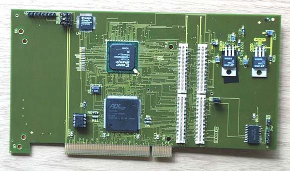
- PLX9054 PCI master bridge chip
- PCI 2.1 and 2.2 compliant
- JTAG port to FPGA PROM and FPGA
- CMC (IEEE P1386 Draft 2.3) single size carrier
SIS 1100-cCMC cPCI CMC Carrier board: 3U cPCI CMC (Common Mezzanine Card, IEEE P1386 draft) carrier board. The card is part of the SIS PCI-VME interface, but due to its flexible FPGA based design it can be used as a versatile carrier board for a variety of CMC front end cards.
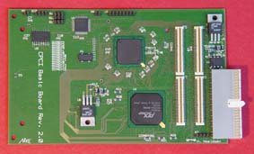
- PLX9054 PCI master bridge chip
- PCI 2.1 and 2.2 compliant
- JTAG port to FPGA PROM and FPGA
- CMC (IEEE P1386 Draft 2.3) single size carrier
SIS1100-ECMC PCI EXPRESS CMC CARRIER/OPTICAL LINK BOARD: Single lane PCI express CMC carrier to be used with CMCs like the FZ Jülich ZEL Scaler CMC. For our PCIe to VME interface or frontend readout systems it is stuffed with one small form factor (SFF) 1/2/4 G link medium.
- Single lane PCIe card
- PLXtech PEX8311 PCIe to local bus bridge
- Xilinx Virtex 4 FPGA
- single CMC site
- SFF 1/2/4 GBit/s optical link option
SIS1100-E2 PCI EXPRESS OPTICAL LINK BOARD: This is follow up card to our SIS1100-eCMC board (without CMC carrier functionality). It was developed to extend the lify cycle of our PCIe to VME interface. For software/driver compatibility reasons we still employ the PEX8311 PCI Express to local bus bridge chip.
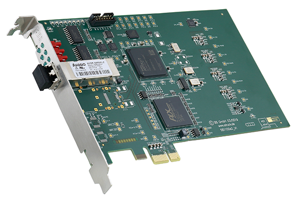
- Single lane PCIe card
- Xilinx Artix 7 FPGA
- PLXtech PEX8311 PCIe to local bus bridge
- SFF 1/2/4 GBit/s LC optical link
SIS1160 8 LANE GEN3 PCI EXPRESS CARRIER FOR DIGITIZER FMCS: Xilinx Kintex Ultrascale FPGA based high performance high pin count (HPC) FMC Carrier with SFP+ cage. Mainly targeted at the use with Struck digitizer FMCs. Sub Nanosecond timing synchronization is available with the White Rabbit (WR) option
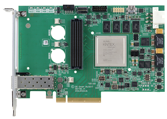
- 8 lane Gen3 PCIe card
- XCKU040-1FFVA1156C Kintex Ultrascale
- HPC FMC Connector
- SFP+ Cage
- 256 M x 16 DDR4 Memory
SIS1350 SINGLE CHANNEL 500 MS/S 12-BIT PCI EXPRESS ADC/DIGITIZER: Developed for high repetition rate acquisition of short analog signals (i.e. up to 128 µs at 500 MSPS) with good resolution
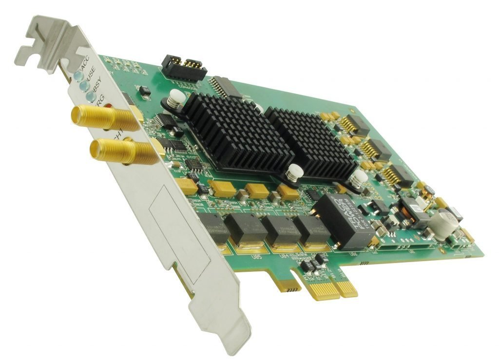
- One channel
- External TTL and internal trigger
- 500 MS/s (10 MS/s – 500 MS/s) internal clock
- 2 x 64 KSamples/channel memory
- 250 MHz analog bandwidth
- Offset DAC
USB Based Electronics
SIS9910 USB2.0 BASED FAST PLC WITH TIGERSHARC DSP: SIS9910 board was developed as the central component of the 2nd generation Inline Seam Control (ISC) system. Due to its flexible design it can be used for many applications that are too demanding for standard programmable logic controllers (PLCs)
- 2 channels of 500 KHz 12-bit ADCs
- 1 channel DAC (settling time 0,6 µs)
- 8 digital inputs (via opto couplers)
- 8 dgital outputs
SIS9965 USB2.0 BASED DIGITAL I/O CARD WITH FPGA: Developed as interface/monitoring module for industrial applications. It is used in the SIS Rollmark detector for shaft encoder supervision and digital I/O e.g. The on board FPGA allows the use of custom firmware for demanding applications.
- USB 2.0
- 8 channels of 24V Digital Inputs
- 8 channels of 24V Digital Outputs
- 4 channels of TTL Inputs
- 4 channels of TTL Outputs
SIS9967 16-CHANNEL 50 MS/S 14-BIT USB2.0 DIGITIZER/ADC: Standalone 16 channel 14-bit digitizer card with USB2.0 and optical link readout capabilities. Two 125 MS/s 12-bit DAC channels allow for control of external hardware and/or implementation of fast feedback systems.
- 16 channels
- 50 MS/s per channel
- 14-bit
- USB2.0 or Optical Link Connection
- 2 125 MS/s 12-bit DACs
- Internal/external Clock
- 8 RS422/485 Serial I/Os
- Servo Motor Control
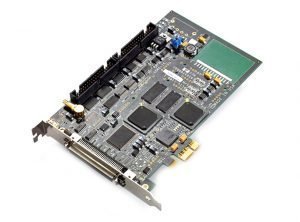
High Performance I/O Boards
Analog I/O Boards: Highest-performance Analog I/O, Digital I/O and Serial I/O products, based upon a variety of buses such as PMC, PCIe, PCI, PC104Plus, VME, cPCI and VPX.
- Up to 64 Input Channels per Board
- Programmable Sampling Rates to 50M SPS
- GPS Synchronization
- Multi-Board Synchronization
- Sigma-Delta and Delta-Sigma Analog I/O
- Resolutions from 12 bits to 24 bits
Digital I/O Boards: High speed digital/parallel I/O boards for embedded applications on several form factors/ buses, operating systems. Cable transceiver options are RS-422, RS-485, LVDS, PECL, and TTL.
- Cable Transfer speeds up to 400 mb/per second
- Large FPGA provides for flexable cable interface
- Available in PMC, PCIe, PCI, PC104Plus, VME, cPCI and VPX
- Support most of Operating Systems
Serial I/O Boards: High speed Serial I/O boards for embedded applications. Transceiver support RS485, RS422 (V.10), RS232 (V.28), RS423, RS530, as well as other software selectable mixed protocol modes.
- Up to Eight Independent Serial Channels per Board
- Synchronous Serial Data Rates up to 10 Mbits/sec
- Asynchronous Serial Data Rates up to 1 Mbits/sec
- Deep Transmit and Receive FIFOs up to 128K
- PMC and cPCI rear I/O support
Sonar Boards: Analog I/O boards for sonar applications on different form factors/buses, and for different operating systems.

- Low skew between channels
- Multi-Board Synchronization
- Sigma-Delta and Delta-Sigma Analog Input
- Up to 64 Channels per Board
- Programmable Sampling Rates to 500K SPS
- Resolutions: 16-bit, 20-bit, and 24-bit
- Form Factor -PCIe, CCPMC
Carrier Boards: Any PMC I/O board can be used on PCI Express, PCI-X, cPCI-X, PCI, cPCI, PC-104-Plus via an adapter
- PCIe Adapters with PMC
- PCIe104x1 to PMC Adapter
- cPCI and PXI with PMC Adapters
- PC104 Plus with PMC Adapters
Serial I/O Boards: High speed Serial I/O boards for embedded applications. Transceiver support RS485, RS422 (V.10), RS232 (V.28), RS423, RS530, as well as other software selectable mixed protocol modes.
- Up to Eight Independent Serial Channels per Board
- Synchronous Serial Data Rates up to 10 Mbits/sec
- Asynchronous Serial Data Rates up to 1 Mbits/sec
- Deep Transmit and Receive FIFOs up to 128K
- PMC and cPCI rear I/O support
Low Cost Data acquisition System
USB Data Acquisition System: Model i60x is the smallest and most accurate electrically-isolated 8channel direct-to-sensor data acquisition system in the world. Connect Windows computer directly to sensors: Volts, Resistance, Current, Thermocouple, RTD, Thermistor, Strain Gage, Load Cell, Pressure, LVDT, Flow and Accelerometer.
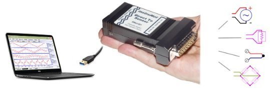
- 16se/8di Voltage Inputs
- 24-bit A/D with ±20mV through ±10V ranges
- Connect directly to sensors
- 4x digital i/o bits
- The i60x is extremely accurate.
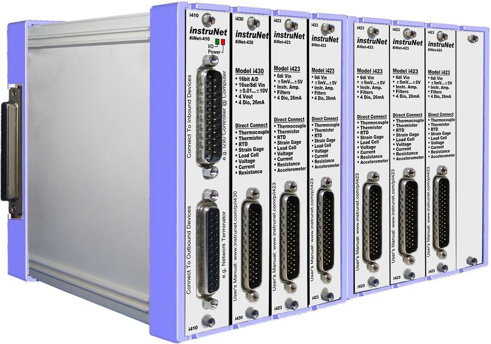
Card Cage DAQ: instruNet i555 System– Cards easily plug into a 4, 8, 12 or 16 slot card cage that communicates with
Windows computer via high speed USB. Low Cost Starter System. Compatible with Excel, LabVIEW, DASYLab, MATLAB, Origin, C & Visual BASIC on Windows. Free instruNet World strip chart recorder software